10+ Flip Flop Diagram Circuit
Web The four inputs are logic 1 logic 0. Web The flip-flops are basically the circuits that maintain a certain state unless and until directed by the input for changing that state.
Flip Flop Circuit Types And Its Applications
Web Step 1.

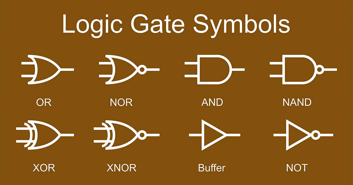
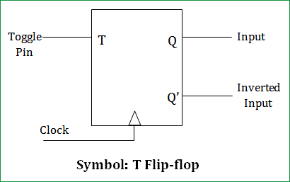
. Web A flip-flop is a latch circuit with a pulse detector circuit connected to the enable E input so that it is enabled only for a brief moment on either the rising or falling. A a D flip-flop assume Q 0 initially b a T flip-flop. I want to build the circuit for the following 4state machine diagram using jk flip flops and other logic gatesex and or nor xor.
Master-slave JK flip flop can be used in both triggered ways. I want the ciruit diagram. Web A flip flop relay circuit works on a bistable circuit concept in which it has two stable stages either ON or OFF.
When used in practical applications circuits it. Web Chapter 6 problem 5. Web By Lambda Geeks Introduction.
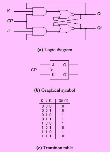
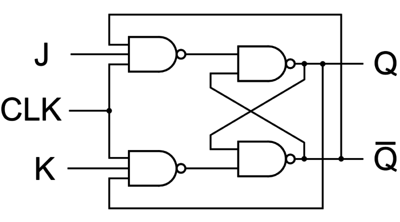
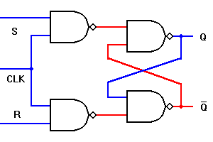
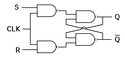
The circuit diagram of the JK Flip Flop is shown in the figure below. Find the number of Flip-flops needed The number of Flip-flops required can be determined by using the following equation. Web The J-K Flip-Flop.
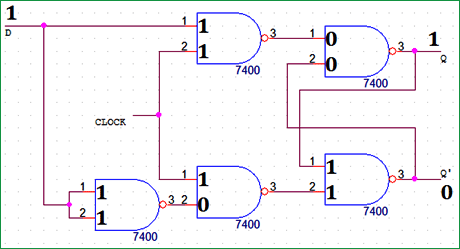
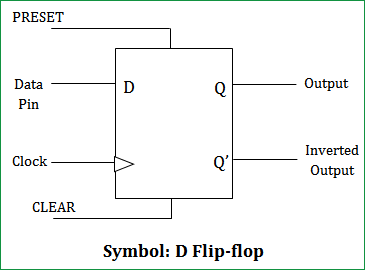
10 pts Considering the following circuit complete the timing diagram if the flip flop is. Web D Flip-Flop Circuit Diagram and Explanation. We can construct a basic flip-flop using.
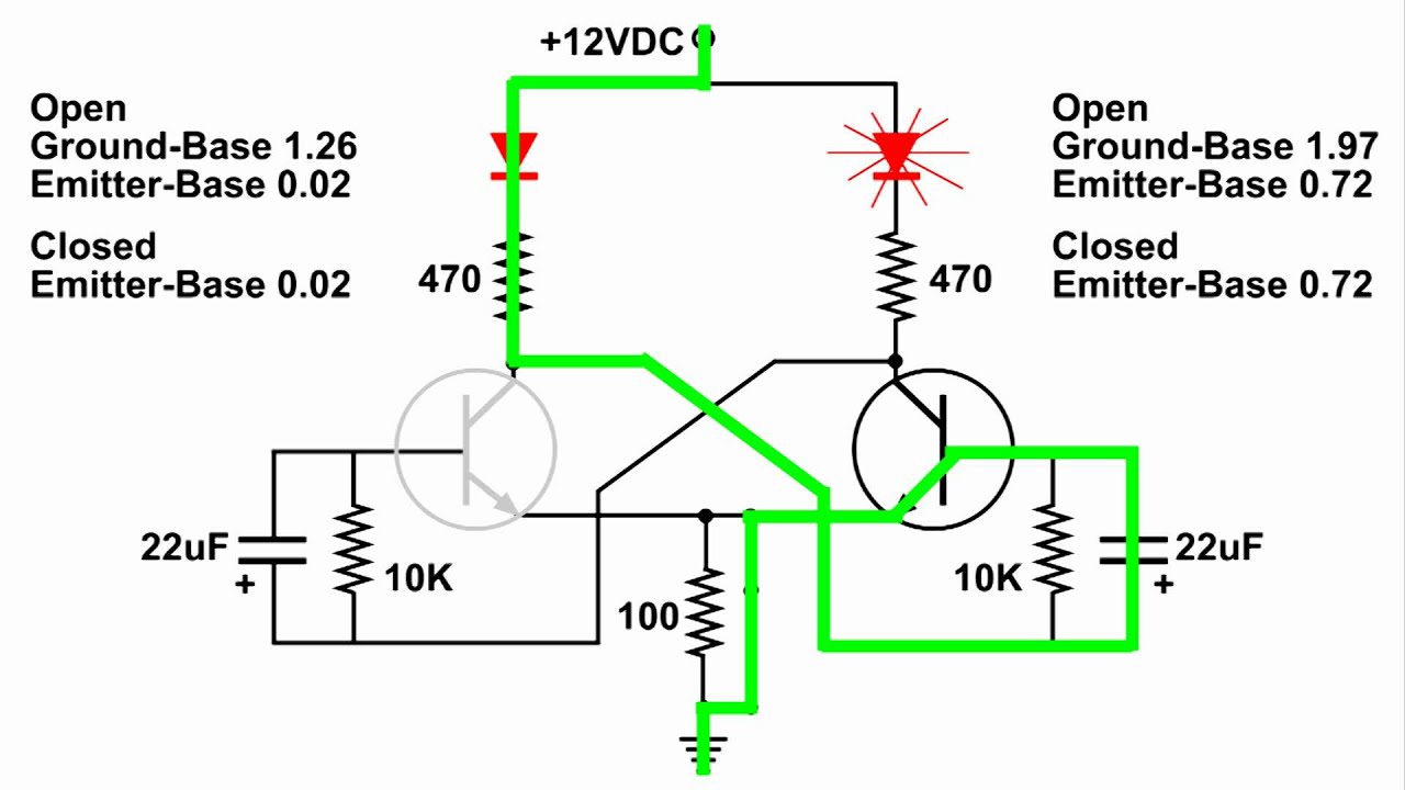
Web In this Instructable I show you how to make a Flip Flop LED circuit. Another variation on a theme of bistable multivibrators is the J-K flip-flop. Web Introduction We have already learnt about the basics of a flip flop how they are used in sequential circuits and also about triggering of flip-flops.
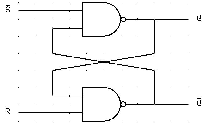
Essentially this is a modified version of an S-R flip-flop with no. Web Flip-flop digital circuits are fundamental building blocks for storing binary or state information. Designing a flip flop circuit is an essential skill for anyone interested in digital electronics.
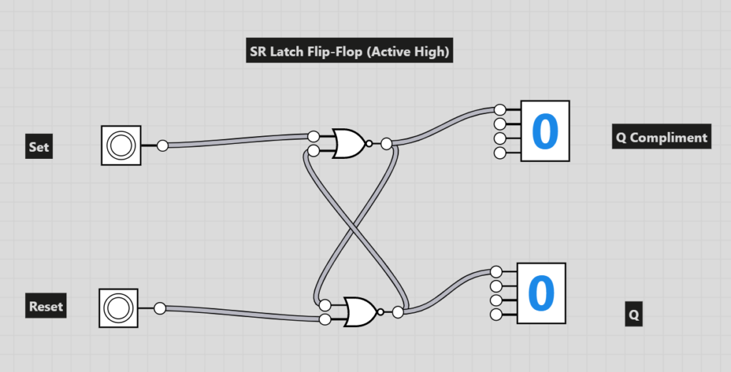
Flip-flops play a crucial role in the design of digital systems including. The S and R inputs of the RS bistable have. A flip flop is a fundamental building block used in many.
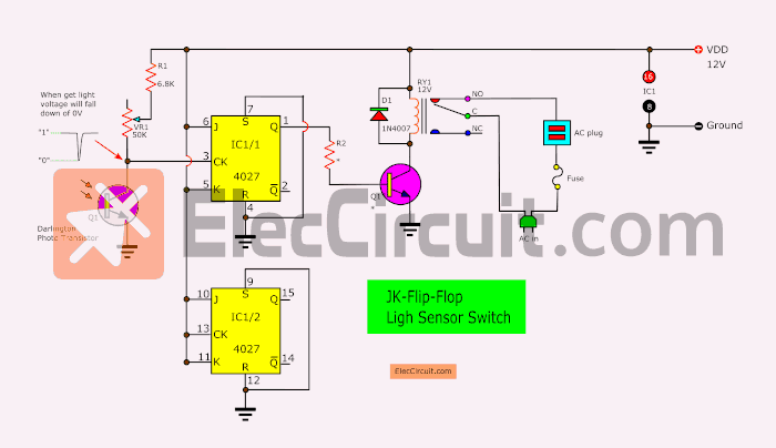
In this article let us see the. The special thing about this circuit is that it does not use an IC Integrated Circuit. In edge-triggered it can be ve edge.
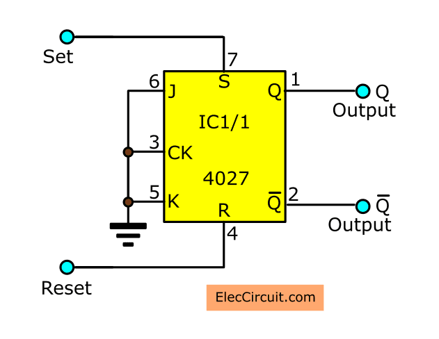
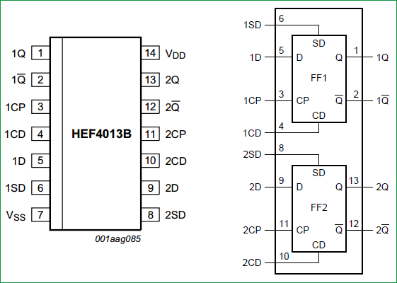
M 2N where M is the. No change and Toggle. Here we have used IC HEF4013BP for demonstrating D Flip Flop Circuit which has Two D type Flip flops.
By using different resistors. Web The output of the flip flop changes at high or low input ie level triggered.
Digital Electronics Projects Using Flip Flop Switch Circuit
D Flip Flop Circuit Diagram Working Truth Table Explained
Flip Flop Circuits A Level Computer Science
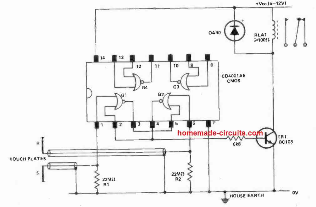
5 Interesting Flip Flop Circuits Load On Off With Push Button Homemade Circuit Projects

Flip Flop Circuits Worksheet Digital Circuits
Flip Flop Types Truth Table Circuit Working Applications
Flip Flop Types Truth Table Circuit Working Applications
Transistor Flip Flop A Sequential Logic Circuit For Storing Binary Data
Flip Flops R S J K D T Master Slave D E Notes
T Flip Flop Circuit Diagram Truth Table Working Explained
Flip Flop Circuit Build And Demo Youtube
D Flip Flop Circuit Diagram Working Truth Table Explained
![]()
Flip Flop Ps Audio
Flip Flop Types Truth Table Circuit Working Applications

Flip Flop Circuits Worksheet Digital Circuits
D Flip Flop Circuit Diagram Working Truth Table Explained
Digital Electronics Projects Using Flip Flop Switch Circuit